panel
—
How an AI engine designs factory-ready furniture from published industry standards — System 32, Blum & Hettich hardware data, the Minifix joint system, EN 312 board specs — with every number derived, every claim gated, and everything unverified honestly labelled until a real factory cut confirms it.
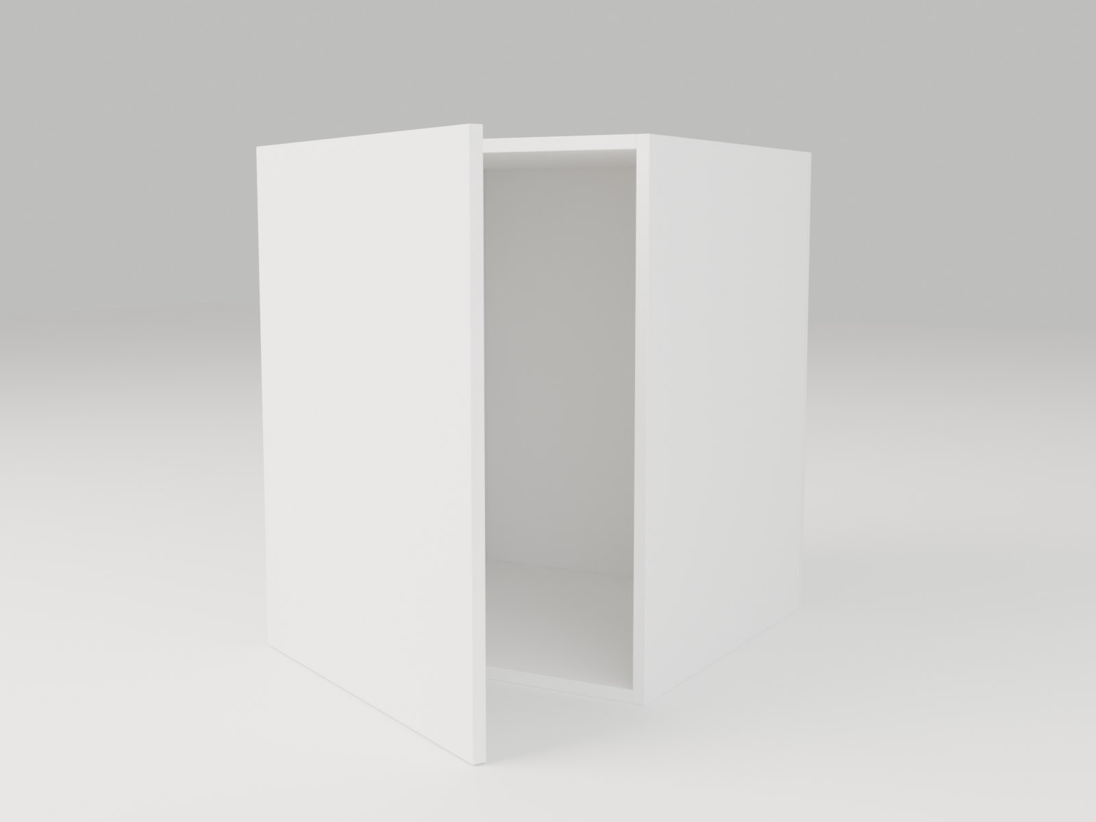
rendered by cycles from the engine's own placements & fittings — nothing hand-modelled
This is not an illustration: every coordinate above is read live from the engine's current model — the same numbers its DXF panel drawings and gcode carry. Ø5/8/15 mm bores run on the gang boring head (System-32 spindles at 32 mm pitch); Ø35 hinge cups run on the router spindle. The real machine file is still gated behind verify-before-the-saw — two deterministic gates plus a human first-cut approval.
The full book is a living document in the engineering repo (KAI Engineering/Kerf/The Kerf Method — Engineering Book.md), written and updated by the same R&D loop that builds the engine. The models it describes are on the Flagship Advancement page — orbit them, open the doors, explode the joints; the hardware you see is placed by the rules in these chapters.